If you’ve ever stood on the floor of a steel mill, watched a construction crane lift a 20-ton steel beam, or seen a plastic molding press compress molten resin into a intricate automotive part, you’ve witnessed industrial hydraulic systems at work. These systems are the unsung workhorses of manufacturing, construction, and heavy industry, turning pressurized fluid into the raw power that keeps operations moving. Over my 12 years as an industrial hydraulic systems supplier, I’ve sat across the table from plant managers and maintenance leads who ask the same core question: Is an open-loop system right for my application, or do I need a closed-loop setup? It’s not a trick question—they don’t realize how much a single choice here will impact their energy bills, maintenance downtime, and long-term operational flexibility. Today, I want to break down the real, practical differences between these two systems, not just as a supplier selling parts, but as someone who’s walked their shop floor and seen what works for a 24/7 metal stamping plant versus a seasonal construction site. Industrial Hydraulic Systems
Let’s start with the basics, because anyone trying to learn this shouldn’t have to wade through jargon to get it. Both open-loop and closed-loop hydraulic systems use Pascal’s principle—pressure applied to a confined fluid transmits force equally in all directions. The difference comes down to how that fluid cycles through the system, and how it’s controlled. That fluid isn’t just “oil” either; it’s the system’s nervous system and power source, so every part of its journey matters.
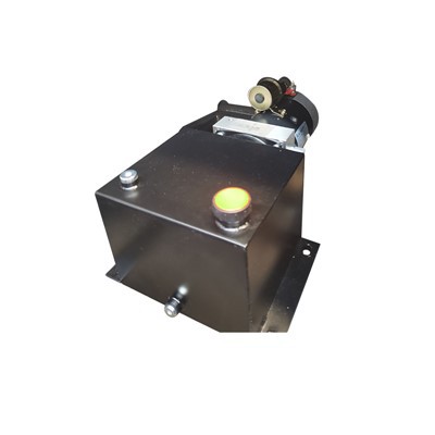
An open-loop system, in its simplest form, is a one-way loop. The hydraulic pump draws fluid from a large, separate reservoir (think of a big metal tank sitting off to the side of the main power unit), pressurizes it, sends it out to the actuator—whether that’s a cylinder that extends a press ram or a motor that turns a conveyor—and then returns the used, low-pressure fluid straight back to that same reservoir. That’s it: out, work, back to the start, no detours. It’s a straightforward design, built for simplicity, and that’s why it’s been the workhorse of industrial hydraulics for over a century.
A closed-loop system, by contrast, is a tight, continuous circuit. The pump doesn’t draw from a large external reservoir—it takes its fluid directly from the outlet of the actuator, and the fluid that comes off the actuator’s other port feeds straight back into the pump. There’s no big, separate tank to hold the bulk of the fluid. All the fluid stays contained between the pump and the actuator, cycling nonstop without ever leaving the core circuit.
Now, let’s talk about how these differences play out in real-world use, because that’s what matters most to someone running a business. Let’s start with control, since that’s the biggest divide. For open-loop systems, the power unit’s operation is controlled by a directional valve—most often a spool valve—that acts like a traffic light for fluid. When the valve shifts, it sends pressurized fluid one way to extend a cylinder, the other way to retract it, or diverts it off to a different part of the system entirely. This means you can have multiple actuators working off the same pump, each controlled independently. For example, in a typical automated assembly line, you might have a clamp cylinder, a lift cylinder, and a rotary motor all running off one open-loop power unit. The spool valve lets you tweak how much fluid goes to each, adjust their speed, and sequence their operations all from one central control panel. That flexibility is a huge plus for mixed-production facilities that switch between parts every few hours. But here’s the catch: because the fluid is always returning to the reservoir, you’re not constantly adjusting the pump’s output to match the load. Most open-loop pumps run at full capacity whenever the system is on, regardless of whether the actuator needs that much pressure or speed. A 50-ton press running at half capacity for a small part is still drawing full power, which means wasted energy and higher utility bills. I’ve seen plant managers run their open-loop systems on old, throttled flow valves just to cut power use, and that leads to overheated oil and accelerated part wear—another cost down the line.
Closed-loop systems fix that energy waste by design, because they use variable-displacement pumps that adjust their output constantly to match the exact load the actuator needs. If a cylinder only needs 10 gallons per minute to move a mold into place, the pump doesn’t push 50 gallons; it slows down to deliver exactly what’s required. That doesn’t just cut electricity use—cutting power draw by 30% to 50% is common with closed-loop setups—it also reduces heat buildup in the fluid, because less excess fluid is being forced through valves and hoses. For applications that require precise, consistent movement, that control is game-changing. If you’re running a robotic welding cell that needs to move a torch within 0.1 millimeters of a seam, or a large turbine blade manufacturing press that has to apply 200 tons of pressure evenly across a 10-foot platen, a closed-loop system can adjust in real time, fine-tuning pressure and speed without the lag you get from open-loop flow valves. But that precision comes with a tradeoff: closed-loop systems are less flexible for multiple actuators. You typically run one actuator per pump, so if you need two separate functions, you’ll need two closed-loop pumps and two separate circuits, which adds upfront cost and takes up more floor space. For a small job shop that runs 10 different jobs a day with different parts, that extra setup might not be worth the precision.
Next up, reliability and maintenance—something I talk about with every client, because downtime costs money faster than any equipment payment. Open-loop systems have a big external reservoir, which might sound like a downside, but it’s actually a reliability strength when it comes to fluid longevity. The large reservoir gives the hot, used fluid time to cool down before it’s pumped back into the system, and it lets contaminants like metal shavings or water vapor settle out—gravity pulls them to the bottom of the tank, where they can be drained off during routine maintenance. The separate reservoir also acts as a buffer; if there’s a leak in a line, you don’t lose all your fluid at once, so the system doesn’t seize up mid-cycle. That’s why open-loop systems are the go-to for construction equipment, agricultural machinery, and any application where the system is exposed to dust, debris, or extreme environmental conditions. I recently worked with a paving company that was running open-loop dozers on a highway project in Arizona’s 110°F heat; the big reservoir let the oil stay cool even during 12-hour shifts, so they only had to change fluid once a season instead of every month. The downside for open-loop, though, is more moving parts, especially those directional spool valves that can wear out from repeated shifting. Every time the valve opens and closes, small metal particles flake off, and over time, that wear can cause leaks or erratic fluid flow.
Closed-loop systems, on the other hand, have very few external connections and no large reservoir, which means less surface area for contaminants to get in. The fluid stays enclosed in a sealed circuit, so dust and moisture are far less likely to sneak in, and there’s less air bubbling through the system (air causes spongy, unpredictable movement in actuators). That makes closed-loop systems ideal for clean, controlled environments like semiconductor manufacturing or pharmaceutical packaging, where even a tiny bit of contamination can ruin a full batch. But the sealed design has a maintenance downside: you can’t just pull a drain plug and let sediment settle. All the fluid is cycled between the pump and actuator, so contaminants stay in suspension much longer, and you have to use specialized filters that are more expensive than standard open-loop filters. Also, if there’s a leak in a closed-loop circuit, you lose all your fluid fast—there’s no big reservoir to keep the system running while you repair the line—and replacing the variable-displacement pump (the heart of the closed-loop system) costs 20% to 30% more than a comparable open-loop pump. I had a client in aerospace a few years ago who tried to cut corners by delaying a closed-loop pump replacement; a 1/8-inch leak on their wing panel press caused a fluid loss that shut down their 24/7 production line for 18 hours, costing them over $120,000 in lost orders. That’s the kind of story that sticks with me when advising clients.
Cost is the final piece of the puzzle, and it’s rarely a one-size-fits-all answer. Upfront, open-loop systems are cheaper to install. The pumps are less expensive, the directional valves are standard off-the-shelf parts, and you don’t have to design a complex sealed circuit. For a small metal stamping shop adding a new 100-ton press, an open-loop setup might cost 15% to 25% less than a closed-loop equivalent. But over the system’s 15 to 20 year lifespan, those upfront savings often get eaten up by higher energy bills and more frequent maintenance. I worked with a job shop in Ohio that switched three of their presses from open-loop to closed-loop in 2021; their energy use dropped by 42% in the first year, and their fluid and filter maintenance costs went down by 28%, even with the more expensive filters. For high-cycle, high-load applications that run 24/7, the long-term savings make closed-loop worth the extra upfront cost. For a seasonal construction company that only runs their equipment 5 months a year, the upfront cost of closed-loop is hard to justify when open-loop works fine.
Let me wrap this up with a real scenario to make it concrete. Last year, I consulted for a mid-sized automotive parts manufacturer that was having problems with their line of door panel presses. They’d been running open-loop systems for 12 years, but as demand shifted to more complex, high-precision panels, their presses weren’t holding consistent pressure—they’d have a few bad parts a week, costing them thousands in scrap. I helped them test both options: they installed a small closed-loop system on one press and kept the original open-loop on a neighboring press. After 3 months, the closed-loop press had a scrap rate of 0.2%, compared to 2.1% for the open-loop one, and their monthly electric bill for that line dropped by $1,200. The only downside was that when they switched to closed-loop, they had to rework their control panel to handle the variable pump, which added a few days of downtime during the changeover. That’s the tradeoff I always explain: closed-loop delivers the precision and efficiency, but you have to plan for the integration, while open-loop is fast and cheap to deploy, but it might not keep up with changing production needs.
At the end of the day, there’s no “better” system—only the right system for your specific operation. If you’re looking for flexibility for multi-actuator setups, low upfront cost, and reliability in harsh conditions, open-loop is probably your match. If you need precise control for high-load, high-cycle applications, long-term energy savings, and a clean, low-contamination environment, closed-loop is the way to go. The worst thing you can do is guess, or go with whatever the cheapest option is today. I’ve seen too many clients spend more fixing a mismatched system than they would have spent upfront on the right one.
If you’re ready to assess your current hydraulic setup, or are looking to design a new system that fits your production needs, feel free to reach out. We work with shops of all sizes, from small job shops to large manufacturing facilities, to find the right balance of performance, cost, and reliability. We don’t push one system over the other—we listen to how you run your operations, how often you need to run equipment, and what your long-term goals are, then present the options that make sense for you. Don’t let an uninformed choice lead to avoidable downtime or wasted money—let’s talk through what works for your application.
Tie Rod Cylinder References:
Hydraulic Control Systems: Design and Analysis. S. Yurkovich, CRC Press, 2005.
Industrial Hydraulics and Pneumatics: A Technician’s and Engineer’s Guide. A. Parr, Newnes, 2011.
Fluid Power Circuits and Controls: Fundamentals and Applications. J. S. Rogers and R. H. Mott, CRC Press, 2014.
Wuhu Zhongye Fluid Equipment Co., Ltd.
We are one of the most experienced industrial hydraulic systems manufacturers and suppliers in China, specialized in providing high quality customized products. Please feel free to wholesale bulk durable industrial hydraulic systems in stock here from our factory. Contact us for quotation.
Address: No. 2, Hexing Road, Sanshan District, Wuhu City, Anhui Province
E-mail: zhongyehydro20@163.com
WebSite: https://www.zhongyehydro.com/
